Interfaz de usuario basada en componentes para Smart TV
El rápido crecimiento y la diversidad de dispositivos tecnológicos que se producen en la actualidad están beneficiando a ámbitos como la "inteligencia ambiental". Esta área trata de integrar las tecnologías de la información en cualquier entorno personal. Sin embargo, para construir software de servicio/aplicación que se adapte a diferentes entornos, es necesario disponer de técnicas que favorezcan este tipo de desarrollo. La ingeniería del software basada en componentes (CBSE) es una disciplina de la ingeniería del software que integra componentes (previamente construidos) para construir nuevos sistemas de software. Este artículo presenta un enfoque CBSE para construir interfaces gráficas de usuario (GUI) en tiempo de ejecución. Se presenta tanto una perspectiva de la interfaz de usuario basada en componentes como un conjunto de relaciones entre componentes. Como caso de estudio, este artículo también describe una aplicación construida para un entorno informático emergente, la Smart TV. También se presenta un ejemplo de ejecución en el que se ponen en común algunas soluciones basadas en la Web para construir interfaces de usuario (por ejemplo, Wookie, W3C Widgets, Node.js).
Proceso de desarrollo
El interés de nuestra investigación es describir cómo construir una interfaz gráfica de usuario basada en componentes en tiempo de ejecución para Samsung Smart TV, sin que nos centramos en el proceso de adaptación. Con el fin de explicar mejor el proceso, vamos a mostrar cómo construir una interfaz gráfica de usuario basada en componentes para Samsung Smart TV, que es la relación de unión entre los componentes y qué tipo hay. Además, mostraremos una secuencia de operaciones entre la aplicación y el sistema. También, presentaremos una aplicación Samsung Smart TV donde se observa una GUI basada en componentes.
- Creación de una interfaz gráfica de usuario basada en componentes para Samsung Smart TV
- ¿Cuáles son las relaciones vinculantes entre los componentes y de qué tipo son?
- Secuencia de funcionamiento
- Samsung Smart TV application
Creación de una interfaz gráfica de usuario basada en componentes para Samsung Smart TV
La investigación se centra en el desarrollo de arquitecturas de software basadas en componentes para interfaces de usuario. Utilizaremos CBUI para referirnos a las interfaces de usuario basadas en componentes. Aunque estas arquitecturas CBUI pueden aplicarse en diversos entornos, actualmente se utilizan exclusivamente para construir sistemas interactivos. La interfaz de usuario en nuestro sistema interactivo, podría ser visualizada en diferentes plataformas soportando diferentes tecnologías.
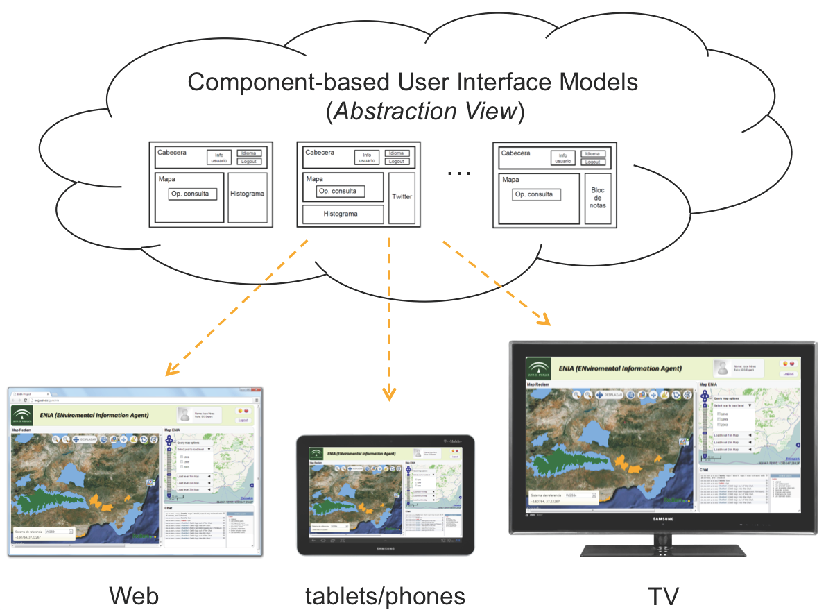
Los desarrollos de aplicaciones para plataformas Smart TV están en auge, y especialmente las aplicaciones desarrolladas para Samsung Smart TV.
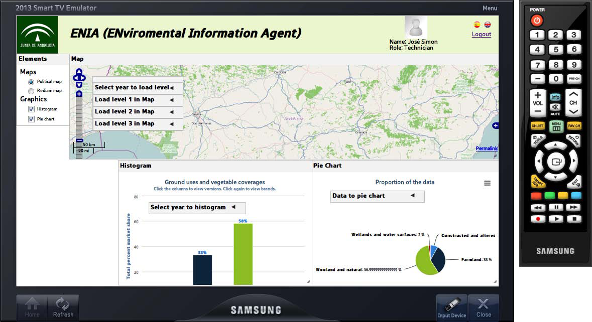
La figura anterior muestra una aplicación CBUI que se está desarrollando para la Junta de Andalucía (España) basada en esta plataforma. Esta aplicación implementa un sistema de gestión medioambiental llamado ENIA2 basado en perfiles de usuario. En esta aplicación, los usuarios interactúan para obtener información sobre usos del suelo y cubiertas vegetales en la Comunidad Autónoma de Andalucía. En este ejemplo, la interfaz está formada por un conjunto de componentes asociados al espacio de trabajo de un perfil técnico de usuario. Dado que la plataforma Samsung Smart TV utiliza una tecnología basada en Web, la aplicación puede adaptarse fácilmente a otros entornos que utilicen la misma tecnología.
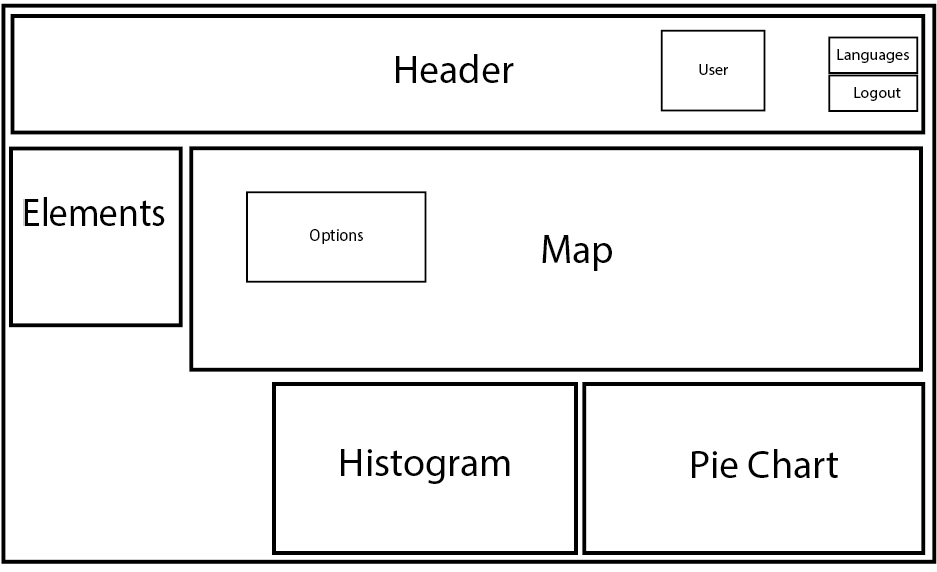
La figura anterior muestra una representación abstracta de esta interfaz. Esta representación facilita la comprensión del funcionamiento de nuestra arquitectura de componentes, ya que permite abstraerse de las características visuales y trabajar sólo con sus características. A partir de esta representación abstracta, se puede crear un modelo abstracto de componentes. Esta abstracción permite describir la distribución y composición de los componentes en la interfaz, dando lugar a un modelo de arquitectura de componentes de interfaz de usuario. Examinemos conjuntamente las dos figuras anteriores. En la parte superior de ambas figuras se encuentra un componente Cabecera. Este componente controla el acceso al sistema y las preferencias de idioma. Para esta tarea, se incluyen en él otros tres componentes: El componente Usuario, utilizado para identificar al usuario, el componente Idiomas, responsable de cambiar el idioma de los componentes de la interfaz y, por último, el componente Cierre de sesión, que cierra la sesión en el sistema conectada al usuario. Todos estos componentes comparten un propósito común, controlar el perfil del usuario. El componente Cabecera es un claro ejemplo de cómo se utiliza el CBSE para crear componentes más complejos integrando otros más básicos.
En la interfaz aparecen otros componentes, utilizados por el usuario para realizar las tareas típicas del dominio de aplicación. El componente Mapa muestra un mapa de la zona de estudio con los resultados de la consulta. El mapa se ha implementado utilizando OpenLayers3. Dentro de este componente se encuentra el componente Opciones, que contiene las consultas que se pueden mostrar en el mapa. A la izquierda del componente Mapa se encuentra el componente Elementos, que permite al usuario seleccionar los componentes que se pueden mostrar en nuestro prototipo de interfaz. Por último, debajo del componente Mapa, hay dos componentes (los componentes Histograma y Gráfico circular) que se utilizan para mostrar información relacionada con la consulta actual.
¿Cuáles son las relaciones vinculantes entre los componentes y de qué tipo son?
Cada componente dispone además de un conjunto de puertos internos por los que se relaciona con otros componentes, lo que permite el intercambio de mensajes entre ellos y proporciona un comportamiento más dinámico y adaptable. La gestión de estas comunicaciones se realiza mediante una serie de funciones incluidas en cada componente. En primer lugar, hay que definir el concepto de relación vinculante. Una relación vinculante es una conexión entre los puertos de dos componentes para entender el funcionamiento de un puerto.
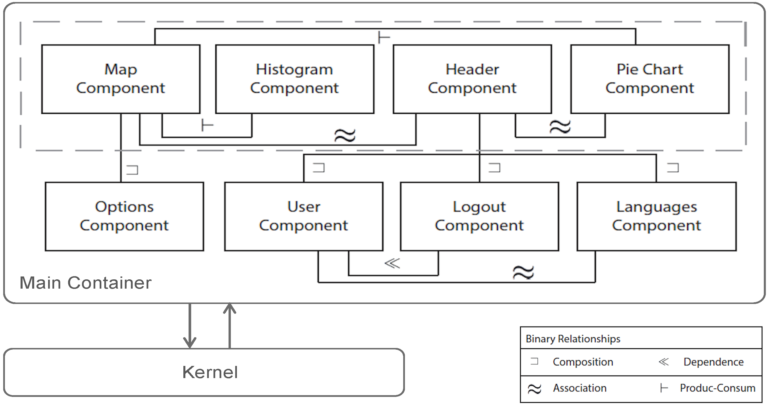
Sólo puede haber una relación vinculante entre dos componentes. Estas relaciones vinculantes ofrecen muchas posibilidades al añadir prestaciones y restricciones al intercambio de información. Existen diferentes tipos de relaciones vinculantes, que se agrupan en dos bloques, relaciones binarias y n-arias. Las relaciones binarias se dan entre un componente y otro. Las relaciones n-arias son un conjunto de relaciones binarias entre un conjunto de componentes relacionados.
Una relación de composición (es decir, entre Map Component y Options Component) muestra que un componente está incluido en otro y no puede ser accedido a través de sus puertos por ningún otro componente fuera de la composición. Podemos ver que existe una relación de composición entre el componente Cabecera y los componentes Usuario, Desconexión e Idiomas.
La relación de asociación (es decir, entre el componente Usuario y los componentes Usuario) entre dos componentes aparece cuando se intercambia entre ellos información necesaria para ambos. El componente Idiomas tiene una relación de asociación con el componente Usuario porque el usuario puede cambiar el idioma de todos los componentes, incluido el componente Usuario.
Existe una relación de dependencia (es decir, entre el componente Usuario y el componente Cierre de sesión) cuando un componente no puede existir o su existencia no tiene sentido sin otro componente. Así, existe una relación de dependencia entre el componente Usuario y el componente Cierre de sesión porque no tendría sentido que existiera un componente Cierre de sesión en la interfaz si no estuviera el componente Usuario.
Por último, la relación productor-consumidor (es decir, entre el componente Mapa y el componente Histograma). Esta relación se produce cuando un componente produce información que es consumida (es decir, utilizada) por otro componente.
Secuencia de funcionamiento
Por último, veamos ahora un ejemplo sobre el rendimiento del sistema. En el ejemplo mostramos los pasos para insertar un nuevo componente en una interfaz de usuario. En el fichero de la página principal de la interfaz de usuario, deseamos insertar el componente Histograma y seleccionarlo del componente Elementos. La siguiente figura muestra el diagrama de secuencia que describe los pasos que sigue el sistema para cargar el componente Histograma. En primer lugar, para iniciar este proceso, el usuario debe seleccionar la casilla Histograma incluida en el componente Elementos (podemos ver esta casilla en la segunda Figura).
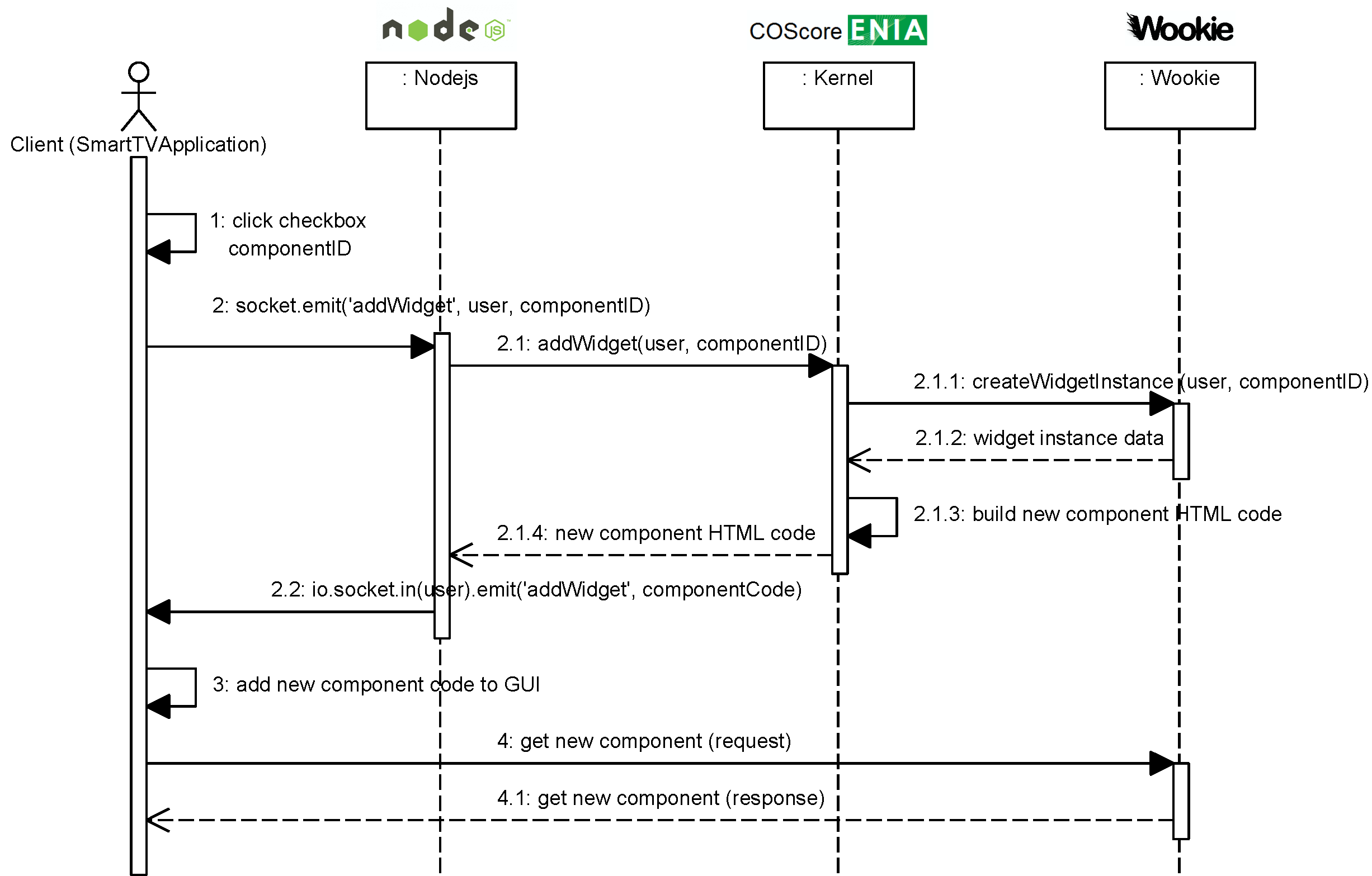
A continuación, el componente Elements emite un mensaje al servidor Node.js. Node.js es un servidor dirigido a eventos haciendo uso de un modelo de entrada/salida no bloqueante, que permite una fácil construcción distribuida de aplicaciones. El uso de este servidor proporciona la capacidad de realizar cambios en la interfaz, como cargar, eliminar, redimensionar o redistribuir un componente dentro de la propia interfaz sin necesidad de recargarla. Node.js emite este mensaje mediante la función socket.emit (mensaje #2 en el diagrama de secuencia). Esta función requiere tres parámetros: el identificador del puerto en el que se emite el mensaje (addWidget en este caso), el propietario de la interfaz gráfica de usuario (denominado usuario), y el identificador del componente que debe insertarse (Histograma en este caso).
Seguidamente, el servidor Node.js invoca la función addWidget del sistema Kernel basándose en la información anterior (mensaje #2.1). Secuencialmente, el Kernel llama a la función createWidgetInstance del servidor Wookie (mensaje #2.1.1). Ahora, Wookie crea una instancia de widget del componente Histograma (componentID) para el usuario indicado y devuelve los datos de la instancia de widget correspondiente para su identificación y uso (mensajes #2.1.1 y #2.1.2). Wookie es un servidor utilizado para gestionar nuestro repositorio de componentes, permitiendo desplegar, actualizar y guardar componentes construidos siguiendo la especificación Widget del W3C.
Una vez obtenida esta información, el Kernel construye el código HTML correspondiente para insertarlo en la interfaz de usuario (mensaje #2.1.3). Este código se devuelve al servidor Node.js (mensaje #2.1.4) y se emite a la aplicación cliente, es decir, a la interfaz de usuario (mensaje #2.2). En el lado del cliente, hay una función encargada de escuchar el puerto web socket addWidget y que inserta el nuevo código en la aplicación SmartTV (mensaje #3).
Finalmente, dado que el nuevo código HTML hace referencia a la instancia del widget que reside en Wookie, el cliente realiza una llamada al método GET al servidor Wookie para obtener la nueva instancia del widget (mensajes #4 y #4.1).
Samsung Smart TV application
A continuación, le presentamos la aplicación Samsung Smart TV desarrollada para la Junta de Andalucía (España). Si quieres probar la aplicación Samsung Smart TV, primero debes instalar el simulador Samsung Smart TV. Aquí tienes el manual.
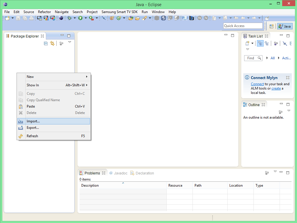
Ahora, debes descargar este proyecto para probar la aplicación Samsung Smart TV. Descomprímelo e impórtalo en el espacio de trabajo.
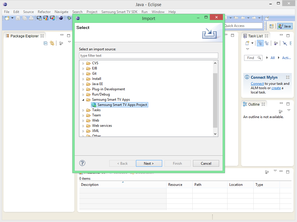
Selecciona Samsung Smart TV Apps Project.
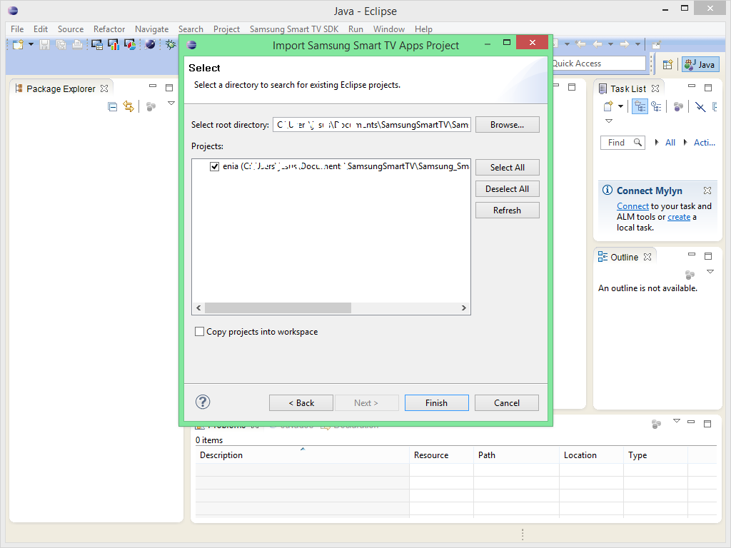
Seleccione el espacio de trabajo y haga clic en Finalizar.
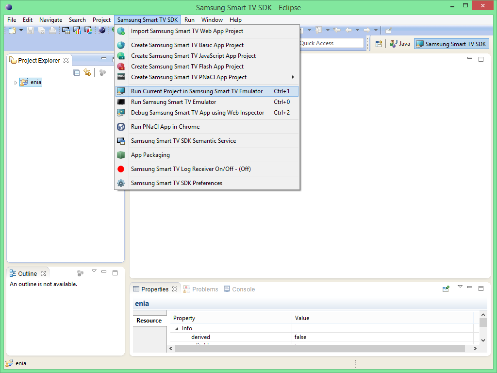
A continuación, ejecuta el proyecto haciendo clic en "Ejecutar el proyecto actual en el emulador Smart TV de Samsung".
Nota
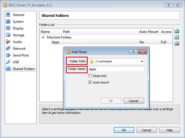
Es muy importante que cuando instale el emulador de Samsung Smart TV las carpetas compartidas del emulador estén en el espacio de trabajo de Eclipse. Por ejemplo, si tu espacio de trabajo está en "C:\workspace", la "Ruta de la Carpeta" debe ser "C:\workspace" y el "Nombre de la Carpeta" debe ser "Apps" en el Emulador. En otro caso, la aplicación no podrá ejecutarse. Preste atención a la información proporcionada en el manual.

P10-TIC-6114
Actualizaciones
En esta API se ofrecen servicios web desarrollados para la gestión de interfaces de usuario mashup.
Un enfoque de interfaz de usuario basado en componentes para Smart TV.
El año 2012 ha sido productivo y, por ahora, se han aceptado tres trabajos.